- Get link
- X
- Other Apps
 |
| Vapor Recovery Units |
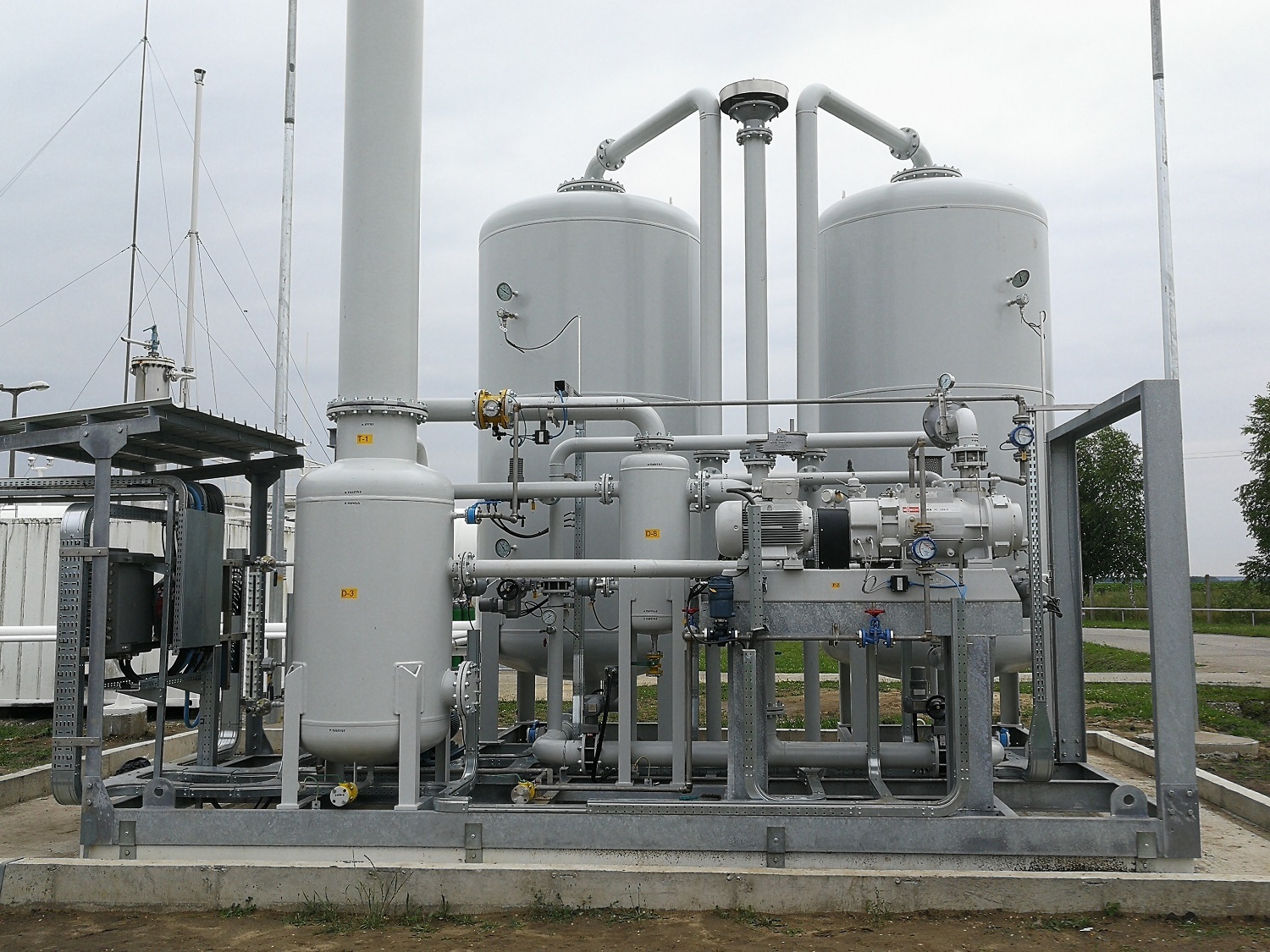
A vapor recovery system is a collection of components that capture vapors that would otherwise escape during the transferring and storage of volatile liquids like gasoline. These systems aim to prevent environmental pollution and recapture vapors for reuse. They are commonly employed at gasoline stations, oil and chemical storage facilities, and petroleum refineries. At the core of most vapor recovery systems are vapor recovery units (VRUs).
How Vapor Recovery Units Work
A vapor recovery unit uses vacuum assistance and vapor-liquid separation
processes to efficiently capture emissions. During storage tank filling or
vehicle refueling, the liquid displaces vapor which is sucked into the Vapor
Recovery Units through hoses or pipes. Inside the unit, an internal
blower or vacuum pump creates negative pressure that pulls the vaporous mixture
in. The vapors then pass through separators which use changes in temperature or
pressure to separate the liquid and vapor phases. The recovered liquid is
returned to the storage tank while the captured vapor is either combusted as
fuel or processed for reuse.
Types of Vapor Recovery Systems
There are two main types of vapor recovery systems - Stage 1 and Stage 2. Stage
1 systems control emissions during the storage and loading/unloading of
gasoline transports and storage tanks. They use coaxial hoses that return
vapors from the tank back to the cargo tank of the delivery truck. Stage 2
systems control gasoline dispensing emissions at the retail fueling site. They
include nozzles with special vapor-capturing adaptors along with piping
manifolds that route gasoline station pump vapors to the VRU for processing.
Components of a Typical Vapor Recovery Unit
A typical vapor recovery unit consists of the following main components:
- Vacuum Blower: Creates negative
air pressure needed to capture emissions. Rotary vane, regenerative, and
centrifugal blowers are commonly used.
- Liquid/Vapor Separator: Allows heavier liquid droplets/mist to separate
out from the vapor stream through techniques like changes in direction,
velocity reduction or cyclonic separation.
- Actuator Valves: Electronically or pneumatically operated valves that
regulate vapor and liquid flow paths within the unit.
- Piping Network: Carries vapor
streams between components through manifolds, conduits and fittings. Made from
corrosion-resistant materials like stainless steel.
- Fuel Storage Chambers: Temporary
holding vessels for recovered liquid gasoline prior to return to storage tanks.
- Sensors and Controls: Measure system operation parameters like vacuum
levels and temperatures. Programmable logic controllers regulate component
operations.
Regulations and Codes for Vapor Recovery
Systems
Strict performance standards and specifications have been set by regulatory
bodies worldwide to minimize emissions from vapor recovery systems. In the
U.S., the Environmental Protection Agency (EPA) developed the Spillage, Liquid
Removal, Vapor Holding and Recovery (SLIVER) test to certify gasoline
dispensing vapor recovery systems under the Clean Air Act. This test requires
that no more than 0.38 lbs of total hydrocarbons and 0.038 lbs of gasoline are
emitted per 1000 gallons of gasoline loaded.
California is among the states with the most stringent rules through its Air
Resources Board (CARB). Stage 1 and Stage 2 systems must meet the Enhanced
Vapor Recovery (EVR) requirements which have tighter emissions criteria than
SLIVER. Transport vessels are certified by testing facilities like California's
BAAQMD and SCAQMD locally. International regulations like Canada's Air Monitor
Directive and Europe's EU Stage II also reference similar protocols for
ensuring vapor recovery compliance. Strict adherence to relevant testing
procedures and certification is critical for vapor recovery systems to
effectively meet air quality standards worldwide.
Advancements in Vapor Recovery
Technology
Significant innovations have been made in vapor recovery technology over time
to boost efficiency and lower costs of compliance. Earlier designs used thermal
(infrared) or catalytic oxidation to combust recovered vapors but had high
energy penalties. Current systems focus more on vapor consolidation and reuse.
Balanced vapor assistance (BVA) utilizes pressure balancing concepts to
transfer vapors more effectively with lower vacuum levels reducing power
consumption. Other recent developments include direct-liquid injection
separators, two-point refueling vapor recovery nozzles, and flexible vapor
piping allowing for above-ground installation versus buried systems. Digital
sensors, networked controls and Internet of Things (IoT) integration are
introducing opportunities for remote monitoring and predictive maintenance of
vapor handling equipment as well. As regulations continue to tighten,
advancements in vapor recovery unit design and performance will remain critical
to enabling cost-effective compliance across refueling and liquid transfer
industries worldwide.
Get more insights on Vapor Recovery Units
Comments
Post a Comment